the XOR method
October 22, 2025. An apartment garage. I'm sitting in my Ioniq 6 with a $15 Vlink ELM327 BLE dongle plugged into the OBD-II port and a MacBook running a Python script I wrote twenty minutes ago. The script connects to the dongle over Bluetooth, sends AT commands to initialize the ELM327, and requests UDS PID 0x220101 from the BMS at CAN address 0x7E4. The response comes back as nine CAN frames, ISO-TP multi-frame, 62 bytes total. I have no idea what any of the bytes mean.
Four days later I'll have decoded 35 fields across 8 PIDs, built a real-time battery monitor, and written a PID scanner that maps the entire BMS address space. A month after that I'll have cracked a door lock checksum and found the CAN channel the BCM uses to lock the car internally, without the key fob.
This is the story of the first two months.
talking to the BMS
The Ioniq 6's diagnostic bus (D-CAN) is accessible through the OBD-II port on pins 3 and 11, not the standard pins 6 and 14. This non-standard assignment is something I'd rediscover the hard way months later when wiring custom hardware. The BMS listens at CAN address 0x7E4 and responds on 0x7EC, at 500 kbps. Communication uses UDS (ISO 14229) over ISO-TP (ISO 15765-2), the same protocol stack that dealer tools and Car Scanner use.
The ELM327 handles the low-level CAN framing. From the Python side, the sequence is:
ATZ          # reset
ATE0         # echo off
ATH1         # show CAN headers
ATSP6        # ISO 15765-4, 500 kbps, 11-bit
ATSH7E4      # set TX header to BMS address
2201 01      # UDS ReadDataByIdentifier, PID 0x0101
The response arrives as a First Frame (10 3E 62 01 01 ...) followed by eight Consecutive Frames (21 ... through 28 ...). After ISO-TP reassembly and stripping the 3-byte UDS header (62 01 01), you get 59 bytes of raw BMS data.
Those 59 bytes contain everything: pack voltage, current, power, state of charge, module voltages, coolant temperatures, operating time, and a set of status flags. The problem is figuring out which bytes mean what.
the XOR method
I had two captures: one with the car idle, one while AC charging. Comparing them byte-by-byte revealed exactly which bytes changed between states.
Byte 4 shifted from 0x32 (50 decimal) to 0x34 (52). Divided by 2: 25.0% to 26.0%. That's SoC, and the formula is byte / 2 = percent. Confirmed against the dashboard.
Byte 11 was the interesting one. Idle: 0x03 (0b00000011). Charging: 0x81 (0b10000001). Bit 7 flipped from 0 to 1 during charging and back to 0 when idle. That's the HV charging flag. Bit 0 toggles independently, BMS ignition/awake status.
byte 11 map:
  bit 7 (0x80): HV_Charging  -- 1 = charging active
  bit 1 (0x02): unknown      -- toggles during idle
  bit 0 (0x01): BMS ignition -- 1 = BMS awake
Bytes 5-8 were all zeros when idle and populated during charging, available charge power and current limits that the BMS only reports when a charger is connected.
This XOR-compare approach turned out to be the single most useful technique in the entire project. Capture two known states, diff the bytes, and the changed ones are your signals. I'd use it hundreds more times over the next nine months.
the PID scanner
The BMS responds to UDS Service 0x22 (ReadDataByIdentifier) with 16-bit PIDs. The address space is 0x0000 to 0xFFFF. I wrote pid_scanner.py to walk through ranges and record which PIDs return a positive response (0x62) versus a Negative Response Code.
Result: 44 responding PIDs out of the ranges I scanned. Most of the interesting ones clustered in the 0x2201xx range:
| PID | Size | Content |
|---|---|---|
0x220101 | 59 B | Pack status: SoC, voltage, current, power, status flags, operating time |
0x220102 | 36 B | Cell voltage group 1 |
0x220103 | 36 B | Cell voltage group 2 |
0x220104 | 36 B | Cell voltage group 3 |
0x220105 | 46 B | SoH, coolant temps, power limits, cumulative energy |
0x220133 | 14 B | Battery module temperatures B01-B07 |
0x220135 | 68 B | Per-module SoH (modules 1-16) |
0x220136 | 68 B | Per-module SoH (modules 17-28) |
0x2201F2 | 180 B | BMS charging time estimates at 50/100/175 kW |
The cell voltage PIDs contain unsigned 16-bit big-endian values scaled by / 50 to get volts. The 54 kWh pack has 96 cells in series (~3.6V nominal each, ~400V total). Between these three PIDs and a few similarly-sized ones I'd discover later, I could read every cell individually.
cracking the temperature encoding
Module temperatures (PID 0x220133, bytes 4-10) were the hardest to decode. The raw values (117, 118, 119) didn't map to any obvious temperature scale. Not Celsius, not Fahrenheit, not tenths of either.
I worked backwards from Car Scanner. It showed module B01 at 20C. The raw byte was 0x76 (118). The offset: 118 - 98 = 20. I checked the other six modules. All matched with the same -98 offset.
"battery_module_temps": {
    "decode": lambda b: [b[i] - 98 for i in range(4, min(11, len(b))) if b[i] > 50]
}
Car Scanner showed 5 module temperatures. My decoder showed 7. First small win.
what the script could do
By the end of October 26 I had a working real-time BMS monitor that decoded more fields than I expected. The script could read individual cell voltages across multiple PIDs, 7 module temperatures, 28 per-module SoH values, pack-level power limits, cumulative energy counters, and round-trip efficiency, on top of the basics like SoC, voltage, current, and charging status.
The BMS's own charging time predictions came from PID 0x2201F2. Bytes 8-9: time to 80% at 50 kW. Bytes 21-22: time at 100 kW. Bytes 114-115: time at 175 kW. These are the BMS's internal estimates based on battery temperature and SoC, not a simple energy-remaining calculation.
All of this from a $15 dongle and a Python script running on a laptop in an apartment garage. No special hardware, no dealer tools, no leaked documentation.
switching buses
Five days later, October 31. I'd been reading BMS data through UDS queries on the D-CAN bus. But diagnostic queries are request-response, the BMS only talks when you ask. For a telemetry device that monitors the car passively, I needed the body CAN bus (B-CAN), where ECUs broadcast state continuously without being asked.
I wired an ESP32-S3 dev board with a CAN transceiver to the B-CAN lines on the OBD port and started capturing.
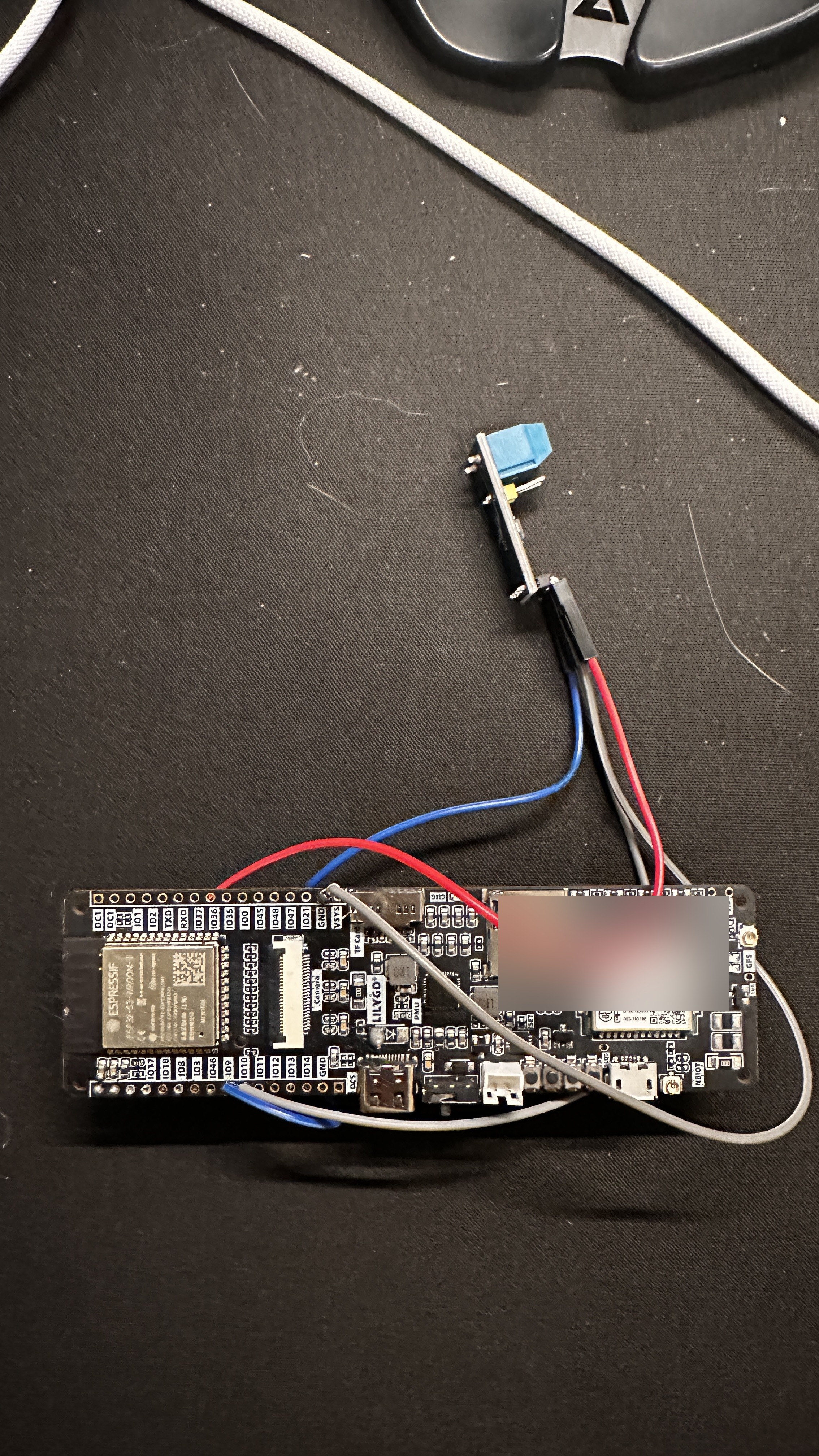
The first baseline capture showed 194 unique CAN IDs broadcasting continuously, a mix of standard 11-bit and extended 29-bit identifiers.
That night I sat in the car and ran 37 systematic tests. Turn on the left signal, capture 10 seconds. Turn it off, capture. Lock the doors, capture. Open the trunk, capture. Change the gear. Press the brake. Cycle the ambient lighting. Each test compared against the baseline to find which IDs changed and how.
Three new CAN IDs appeared that weren't in the baseline:
| ID | Trigger | Type |
|---|---|---|
0x05F | Ambient light control | Periodic while active |
0x4AD | Ambient light brightness | Periodic while active |
0x4D6 | Door lock/unlock | Event-only (single shot) |
0x4D6 was the most interesting. It appeared only during lock/unlock operations -- an event frame, not a periodic broadcast. That made it a candidate for replay: if the car sends this frame when you press the lock button, maybe sending it yourself would lock the car.
Turn signals decoded cleanly. CAN ID 0x413, byte 2: 0x10 = left, 0x40 = right. Byte 0 is a counter/checksum.
the door lock problem
November 17. I'd been trying to lock the car via CAN injection for three weeks. The first target was 0x4D6, the event frame from the inside door lock button.
The frame format: [checksum] [counter] [command] [0x00 x5]. Counter increments by 0x10 per action (0x00, 0x10, 0x20, ... 0xF0, 0x00). Command 0x01 = lock, 0x04 = unlock. The checksum is a per-counter lookup value, not algorithmic.
I built a lookup table from captured frames, tracked the live counter by monitoring 0x4D6 on the bus, and injected frames with the correct next-counter and checksum.
It worked. The doors locked. But the security system didn't arm. No hazard flash, no mirror fold, no "armed" indicator. Just a mechanical click. For a product, this was useless, you need the alarm armed, not just the latches engaged.
the 0x4E4 dead end
The key fob uses CAN ID 0x4E4. When you press the lock button on the fob, the car locks and the alarm arms. So I went after 0x4E4.
Same approach: capture fob lock/unlock events, build a checksum lookup table, track the counter, inject. I captured 25 out of 48 possible checksums (the table has 16 counter values times 3 commands). Good enough for a test.
I injected a valid frame. Nothing happened. Tried again with a different counter. Nothing. Tried every counter value I had a checksum for. The car ignored all of them.
The 0x4E4 channel requires RF authentication. The BCM checks that the physical key fob is nearby via its 433 MHz radio before accepting lock commands on this CAN ID. No amount of correct checksums will work without the fob present. The CAN frame is a notification from the fob's receiver to the BCM, not a command the BCM blindly executes.
Three weeks of checksum capture, wasted. Or so I thought.
the auto-lock insight
November 18. I was thinking about how aftermarket auto-lock modules work. There are commercial products that plug into the Ioniq's B-CAN and lock the car 10 seconds after the driver exits, without the key fob nearby. They use only CAN-H and CAN-L wires. No RF, no key fob relay, no magic.
Then the obvious question: when does the car lock itself without the fob?
Answer: auto-lock. If you unlock the car with the fob but don't open a door within 30 seconds, the BCM re-locks it automatically. The fob isn't nearby when this happens, you walked away, the car decided to re-lock on its own.
I captured the auto-lock sequence. The BCM sends the lock command on **CAN ID 0x392**, not 0x4E4. Same frame format: [checksum] [counter] [command]. But 0x392 is the BCM's own internal command channel. It doesn't check for RF authentication because it is the BCM, the module that would do the checking.
I searched every capture file I'd accumulated over the previous month. Between fob operations, door button presses, auto-lock events, and baseline captures, I found checksums for 14 out of 16 counter values for the LOCK command. 87.5% coverage from data I already had.
const uint8_t CHECKSUM_TABLE_392[16][3] = {
    //        IDLE   LOCK   UNLOCK
    /* 0x00 */ {0xAC, 0xEA, 0xFF},
    /* 0x10 */ {0xFF, 0x53, 0x10},
    /* 0x20 */ {0xC3, 0x76, 0xC6},
    /* 0x30 */ {0x7A, 0x2F, 0x7F},
    /* 0x40 */ {0x72, 0x96, 0xFF},
    /* 0x50 */ {0xCB, 0xD3, 0xFF},
    /* 0x60 */ {0xFF, 0x6A, 0xFF},
    /* 0x70 */ {0xA4, 0xFF, 0xFF},  // LOCK missing
    /* 0x80 */ {0xFF, 0x4B, 0xFF},
    /* 0x90 */ {0xB4, 0x08, 0xFF},
    /* 0xA0 */ {0xFF, 0x24, 0x67},
    /* 0xB0 */ {0xDB, 0x9D, 0xFF},
    /* 0xC0 */ {0xFF, 0xC4, 0xFF},
    /* 0xD0 */ {0xFF, 0x31, 0xFF},
    /* 0xE0 */ {0xFF, 0xFA, 0xFF},
    /* 0xF0 */ {0xFF, 0xFF, 0xFF},  // all missing
};
I injected a LOCK command on 0x392 with the correct counter and checksum. The doors locked mechanically, same as 0x4D6. I also got mirror folding to work through a combination of 0x392 and 0x4D6. But it wasn't reliable. The full alarm arm (hazard flash, interior indicator, the works) never happened consistently. The BCM accepted the lock command but wouldn't fully arm the security system the way a fob press does.
0x4D6 and 0x392 turned out to be the two most reliably injectable CAN IDs on the bus. Both produce a mechanical lock. Neither reliably arms the alarm. The fob channel (0x4E4) remains gated behind RF authentication. Getting the full "fob-quality" lock from CAN injection alone is still an unsolved problem on this car.
three channels, one lesson
| CAN ID | What it does | RF required | Mechanical lock | Full alarm arm |
|---|---|---|---|---|
0x4D6 | Inside door button | No | Yes | No |
0x4E4 | Key fob / outside handle | Yes | -- | Yes |
0x392 | BCM internal command | No | Yes | Not reliably |
The month-long door lock saga didn't end in a clean victory. But the insight that made 0x392 findable, when does the car do this thing by itself?, turned out to be the most important question of the entire project. Whatever channel the car's own BCM uses internally is the one that doesn't need external authentication. That principle would apply to almost every problem I'd hit later.
By the end of November I had passive CAN decoding of body state, UDS access to the full BMS, and mechanical door locking without the fob. The OBD dongle and Python scripts were about to be replaced by custom hardware. But that's the next post.
In the next post: I solder a custom PCB, kill it with a capacitor, and learn that 8 KB of stack is not enough for TLS on an ESP32.